I have today a new board to present. It has made for the Nintendo Game Boy Pocket which allows to use a li-ion battery and charge it by USB-C. Same functionalities as the Game Boy Color board but for this another video game console.
Both boards, GBP and GBC mainboard, are too different. That means I have needed to make a new board and match it to the GBP mainboard.
[notification type=”alert-info” close=”false” ]The information you can read in this article may be obsolete, please read also this page where the information is updated every time that something changes.
https://shop.giltesa.com[/notification]
Kit boards
The Game Boy Pocket has the original jack power connector on the top of the board, the rest of the electronic components are on the opposite side. So, it has required to make this kit with 3 different boards.
USB-C board
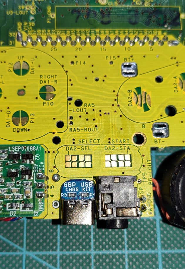
The first board include the USB-C connect with 6 pins (only power) and two resistors. This board has to be soldered on the top side of the GBP mainboard, under the select bottom. There is a few space for this board. It’s connected with the main board using the original pads of the GBP board, that is not an inconvenient because after removing some unnecessary components some track will not have any signal and they will be free for our own use.
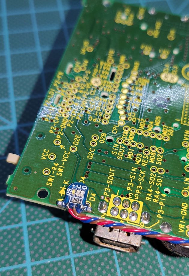
Main board
Last board and the most important includes the electronic components for charging the battery and control the over-discharge of it. It has to be solders on the bottom side. Same as the GBC board, this board includes the TP4056 for charging and DW01A for controlling the over-discharger.

Light board
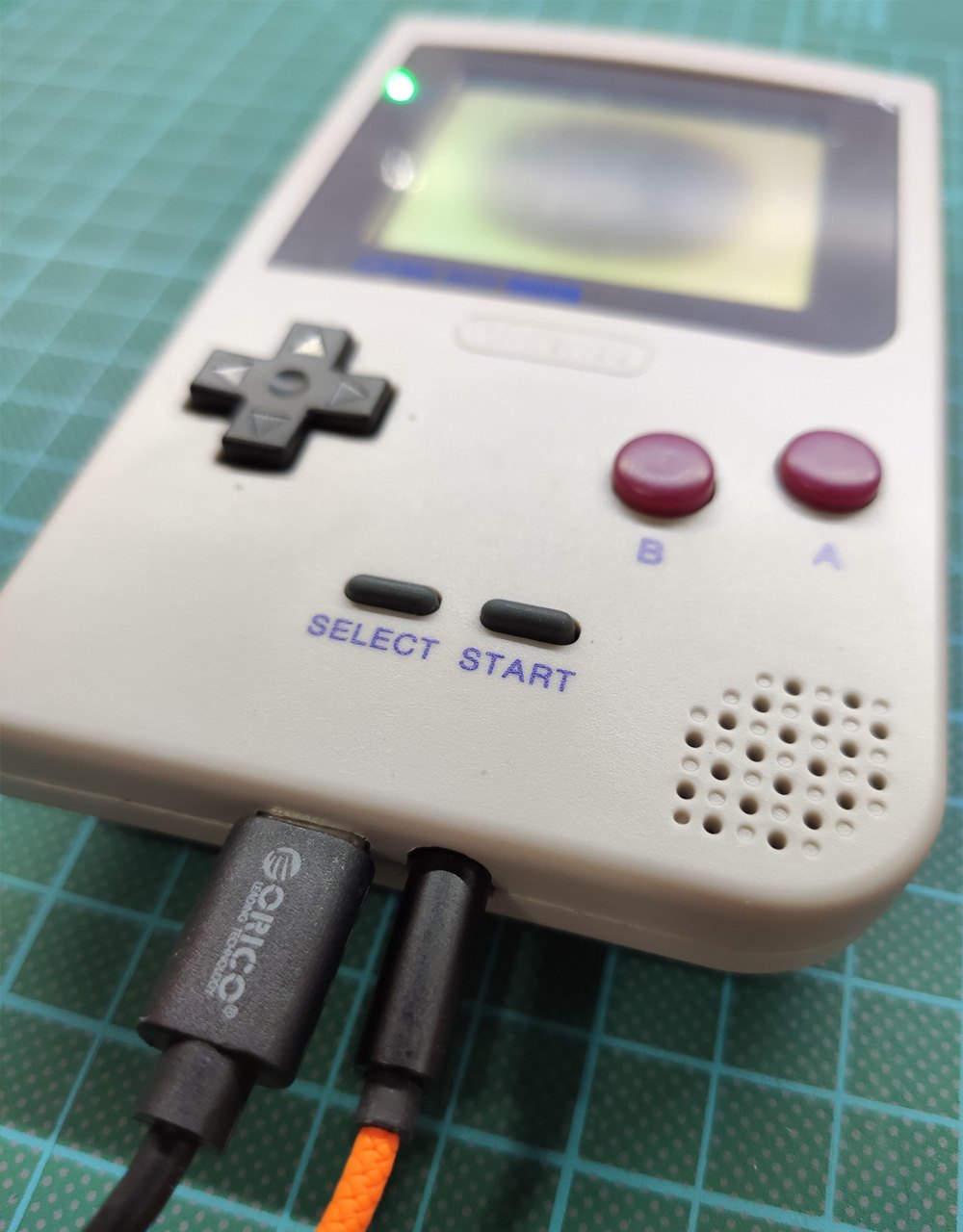
This board include 3 LEDs/lights: white when the GBP is turn on, red when the battery is charging and green when it is full. However if we are playing at the same time that the GBP is connected by USB-C the light colors change: pink (white+red) if you are playing while the GBP is charging, or light green if you are playing while the battery is full.
This board is optional and has to be connected by some cables. There are two possible installations:
If your GBP has the red light, you have to connect the light board to the main board using 3 cables.
Otherwise, you have to solder 2 cables more (GND and VCC). Of course if your GBP doesn’t have light the case don’t have the light hole either, so you will need to replace de case, or minimum the screen glass and make a hole in the original case.
How to install this kit
[notification type=”alert-danger” close=”false” ]This module has been designed to be used with the console’s original voltage regulator because it supports an input voltage range between 2 a 4.6V and the battery kit provide a voltage between 2.75 to 4.2V. If you also want to change the original power supply, it’s important it is compatible with the voltage provided for the battery kit, otherwise you may damage something.[/notification]Clean the Game Boy Pocket mainboard (optional)
Since I only had my own GBP, I have needed to buy another one for testing the board. (I don’t want to modify my own Nintendo collection, not for now).
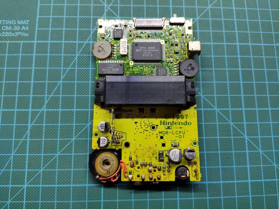
After looking for the cheapest one I was able to find one for 27€. It was dirty of dust, sand and grease. It also has the screen broken, but I don’t care it because I just interesting in the mainboard and this works well after cleaning everything, including the power switch.
It looked like this before cleaning:
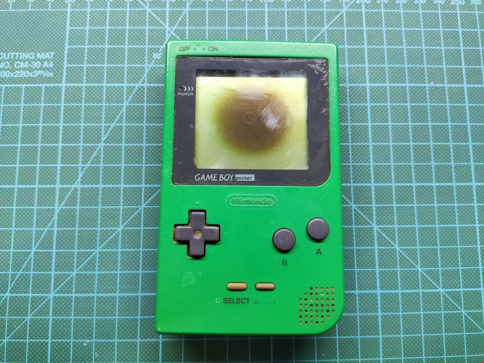
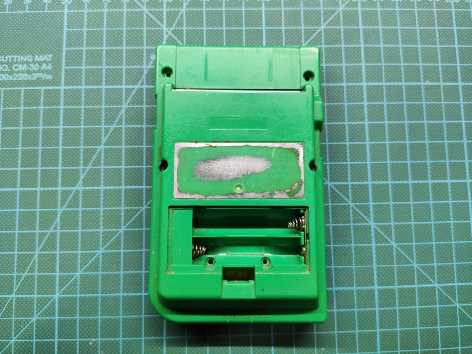
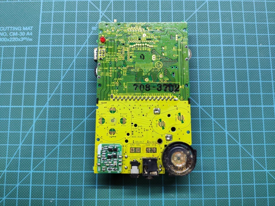

And this after cleaning:
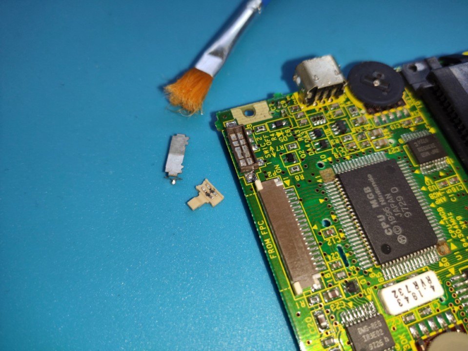
Remove unnecessary electronic components
Because the Game Boy Pocket USB-C Charging Kit will replace the jack and AAA battery, we can remove some electronic components for making space on the board. These components are:
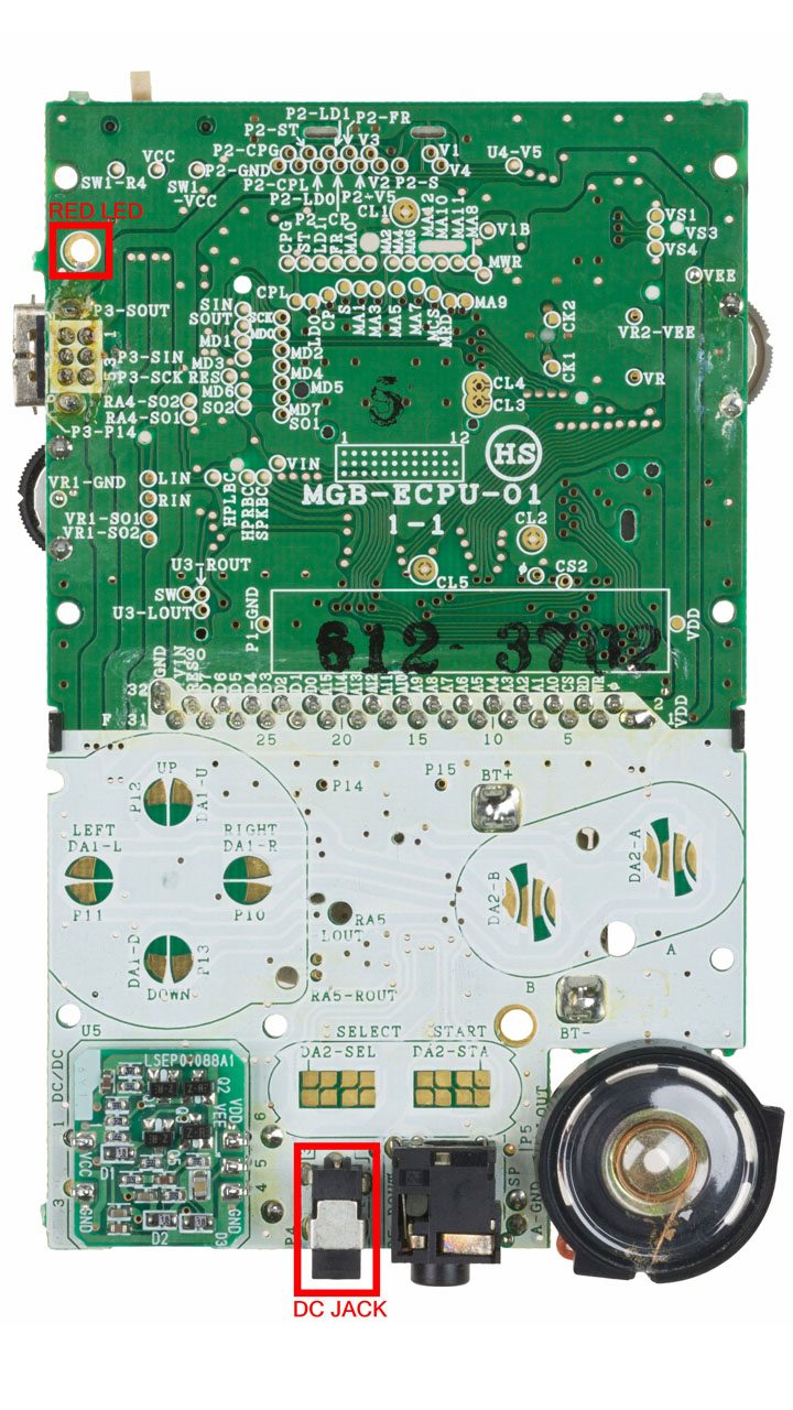
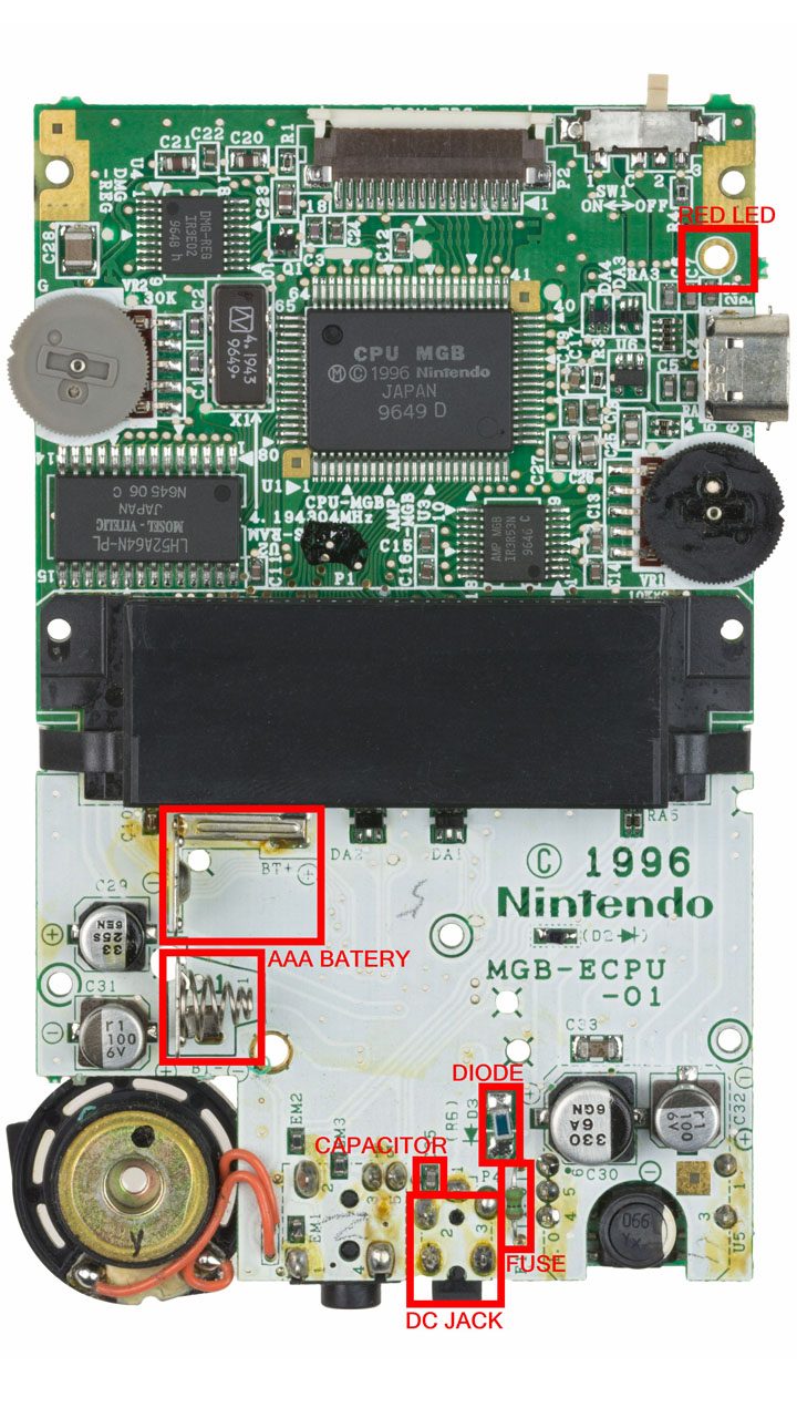
The first version of Game Boy Pocket don’t have red light. However, if you want to add this functionality, the light board include 2 extra pads to connect to some place.
Solder the USB-C board
The USB-C board must be the first one to be installed because the pads are under the board.
-
- After you have removed the GBP jack connector, you have had to clean the holes because you don’t want them full of tin.
- You can preesolder the light board 5V pad, only one!
- Center the USB board in the correct place, be sure you can see the pads of the USB board through the GBP holes.
- Put your solder iron in the VCC hole and the tin will melt.
- Check the board still centred and then.
- Solder all pads.
- Remove the excess of tin because the main board have to be soldered here too.
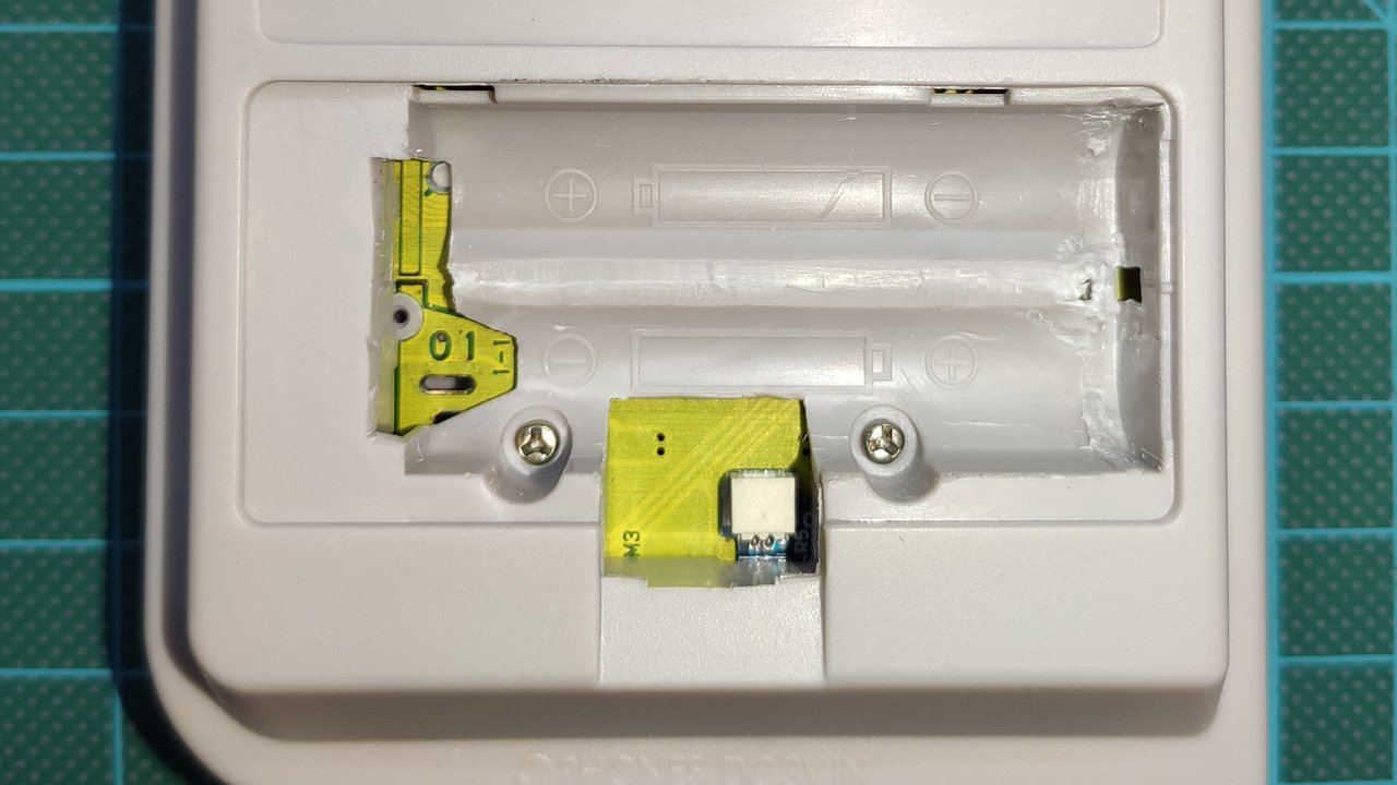
Solder the main board
The main board has 3 points where it has to be soldered to the GBP board. The first point on the top takes the 5V from the USB-C. The second point in the middle, provides the energy from the battery to the GBP. And the last one is the ground/GND.

Solder the light board (optional)
The light board can be a bit hard to solder because it’s so tiny. You can do these steps for soldering it easy.
-
- Pre solder both button pads
- Put the board on its place.
- Put flux in the opposite side of the LED
- Hot both pads and you will see how the pre soldered pads melt.
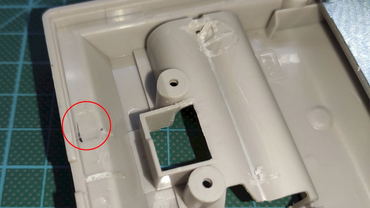
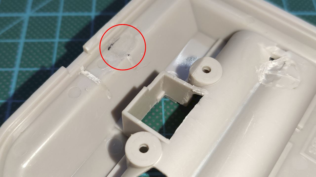
Make the case hole for the USB-C board
You will need to make the jack hole a bit bigger because the USB-C requites that.
You may also need to remove a bit of plastic in this place because some cases can not close well (they touch the electronic of the kit)
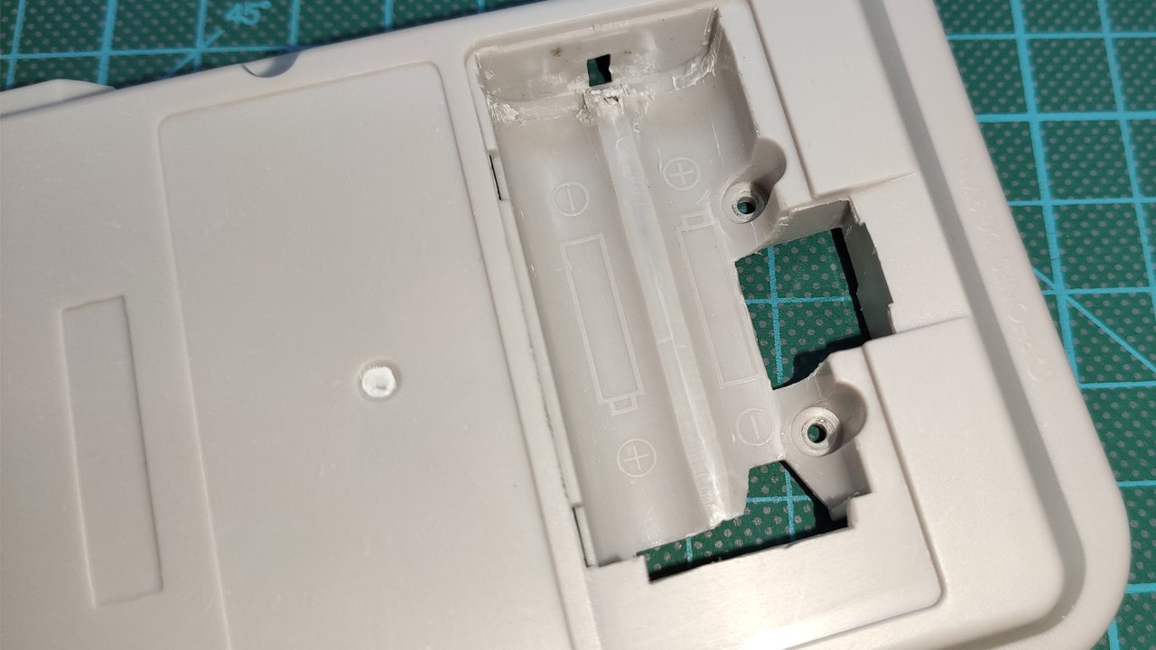
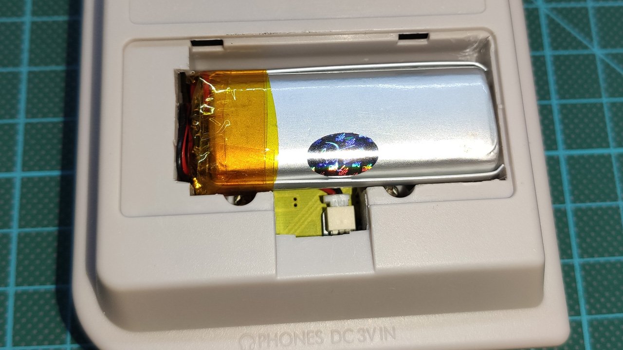
Make the case hole for the main board and battery
I haven’t token any picture when I was making the hole, but you can see how if you cut very well the plastic, you can put a 1500mAh battery (the same as my GBC)


What battery size or part number did you use??
Hello Troy,
I’m using this one:
https://github.com/giltesa/Game-Boy-Pocket-USB-C-charging-kit/tree/master/3.%20Documentation/Battery
Kind regards!
@GILTESA retrogamerepairshop.com don’t ship to the UK. Can you point me to another reseller please.
Hello Fasih,
I just work with that shop, but you can buy it from me directly, I send it to any country. However I don’t have boards right now, I shroud receive them in 2 or 3 weeks.
You can fill the form now and I will send a email to you when I have the boards.
https://forms.gle/1gK1z9QwpREnyB9P6
https://giltesa.com/en/nintendo-usb-c-charging-kit
Kind regards.
Can you explain why this is not work on the MGB-CPU-01 model is there any work around?
Hello Green,
Yes, you can see here the problem and the fix:
https://github.com/giltesa/Game-Boy-Pocket-USB-C-charging-kit/blob/master/3.%20Documentation/Incompatibility%20MGB-CPU-01.pdf
Hello, I was wondering if you could tell me what size the white power led is. So I can order some resistors. I”m trying to get this to work on a CPU-01 and am jumping power to it off the main switch and don’t want to burn it out. Even with the fix you posted the power LED isn’t working only charging red LED is.
Hello Hob,
The information in this page is a bit outdated. You need to connect it like the step 4 says:
https://github.com/giltesa/Game-Boy-Pocket-USB-C-charging-kit/blob/master/3.%20Documentation/USB-C%20Charging%20Kit%20-%20Quick%20Guide.pdf
The LEDs has 0402 size, the resistor is 0603
Kind regards,
Alberto.
Thank you for getting back to me so quickly. Just read though the linked page, so if I wire it this way no resistor extra is needed?
No, you don’t need a extra resistor, the light board include one so it0s safe to connect directly.