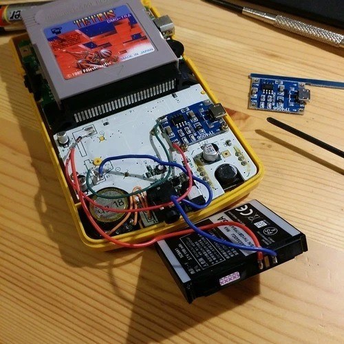
After finishing my year of study and getting my graduation in New Zealand I had about 3 months with too much free time on weekdays. Then, I started to see videos on YouTube and I finally saw some videos about the Game Boy Color and how to modify the video console to improve it. One of these modification is change the original screen for a IPS screen with backgraund illumination, I will show that in another article. The another typical modification is modifies the way to provider energy to the GBC, that is this article is about.
https://shop.giltesa.com
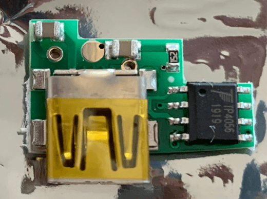
These videos cover some methods of replacing the AA batteries for using something to allow to charge the GBC. The most popular option is using the TP4056 chip which can charge a battery by USB. The way to implement this chip can be using a module from AliExpress or with a personalized circuit.
It’s this second option that most caught my attention, but I discarded it because it use a MiniUSB connector. Then, I decided to make my own board from scratch.

I was clear about some things from the beginning: I wanted the connector for charging was a USB-C. The PCB could be soldered over the original one to avoid to solder any cable. I also wanted the case needed to be cut the less possible. Then, I designed something like this:
The idea wasn’t bad, but everything was too cramped, and the measurements weren’t 100% correct because I couldn’t get the exactly size of the GBC circuit. I also wanted to put the status LEDs on the original red LED pads.
After arriving to Spain and being bored again, I retook the circuit design. The essence is the same but this time I could take the measurements and make my pcb fit perfect on the original pcb. I also checked all conectors (USB, battery, power pads) are in the correct place.

Thanks to the GBC data sheet, I could remove all unnecessary components on the GBC circuit as resistor, capacitors, etc. That helped me to get more free space and distribute better the components for charging the battery.

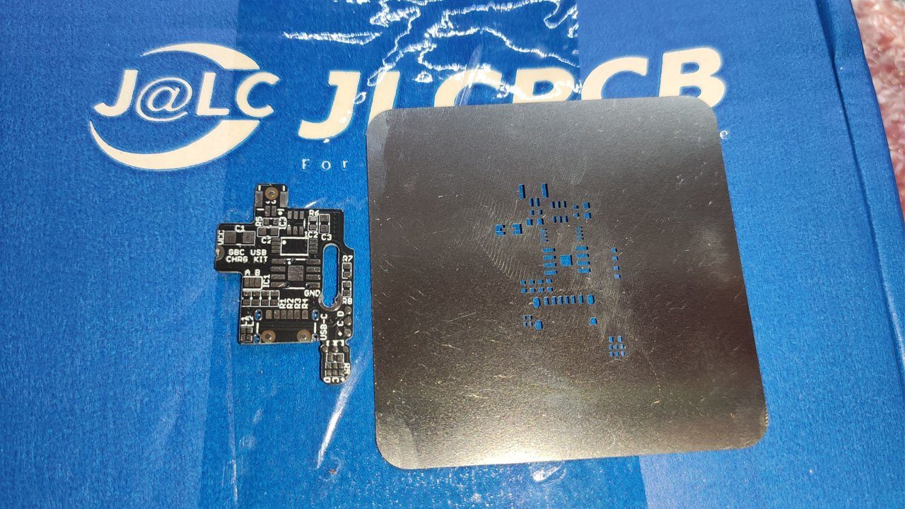
Finally, I ordered the manufacturing of the boards. I used this time the JLCPCB company because the cheap stencil service, I wanted to try it!
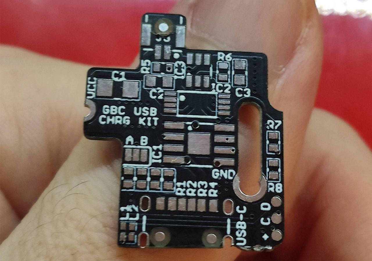
It was the first time I did a order to this manufacturer of PCBs, and to be honest I don’t have anything to complain. The price is so cheap, the shipping time is so fast, only two weeks! After ordening my boards they contacted me because I did something wrong, so I could fix and sent to them the fixed files.
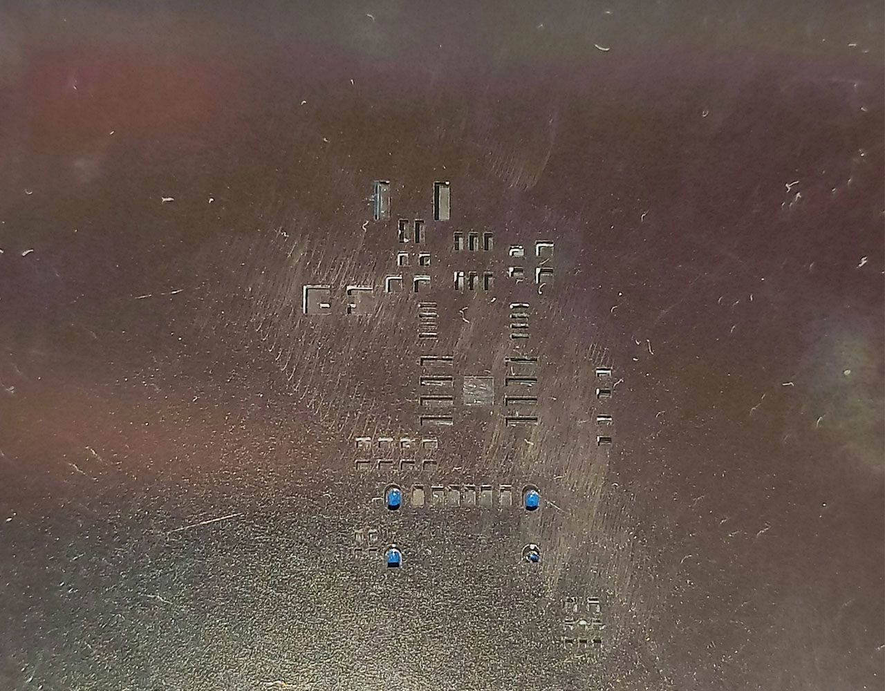
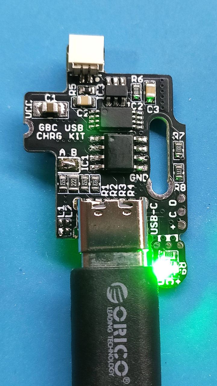
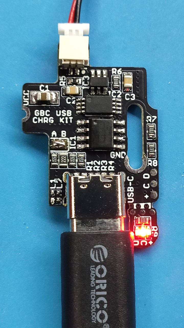
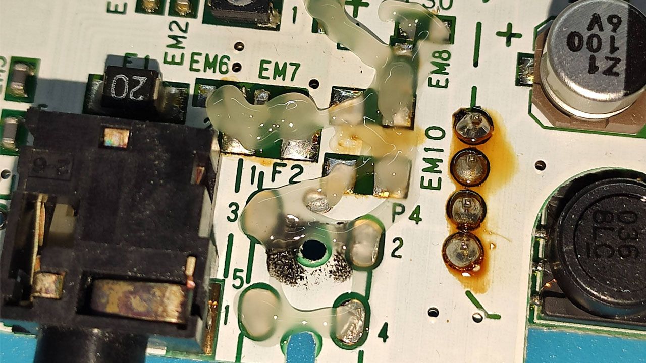
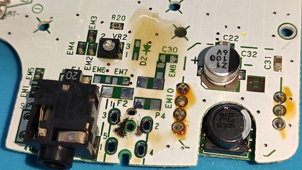
On the following pictures you can see the PCB with solder paste that I applied with the stencil (the paste was too warm, so it was a bit liquid). With some components on the board. When I was soldering it. And finally when i was trying the board.


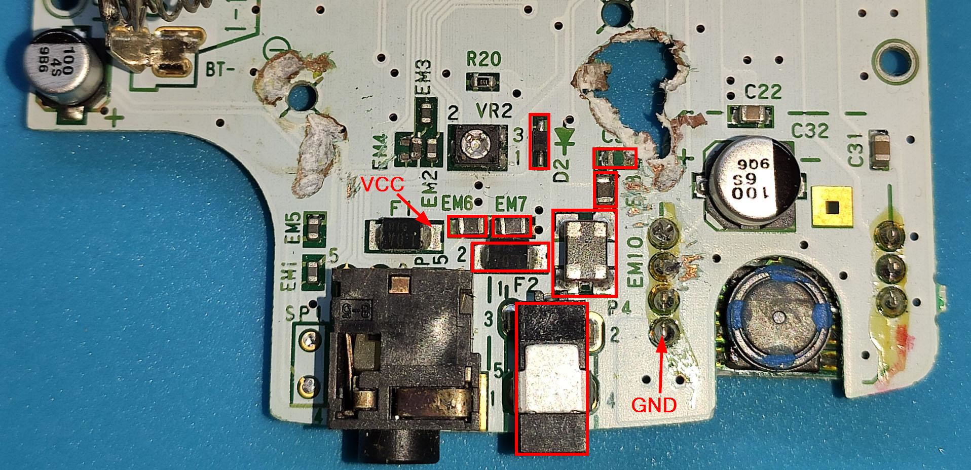
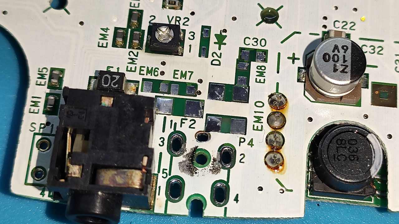
Before soldering the new board, I had to remove the unnecessary components, clean the excess of tin and clean the board:
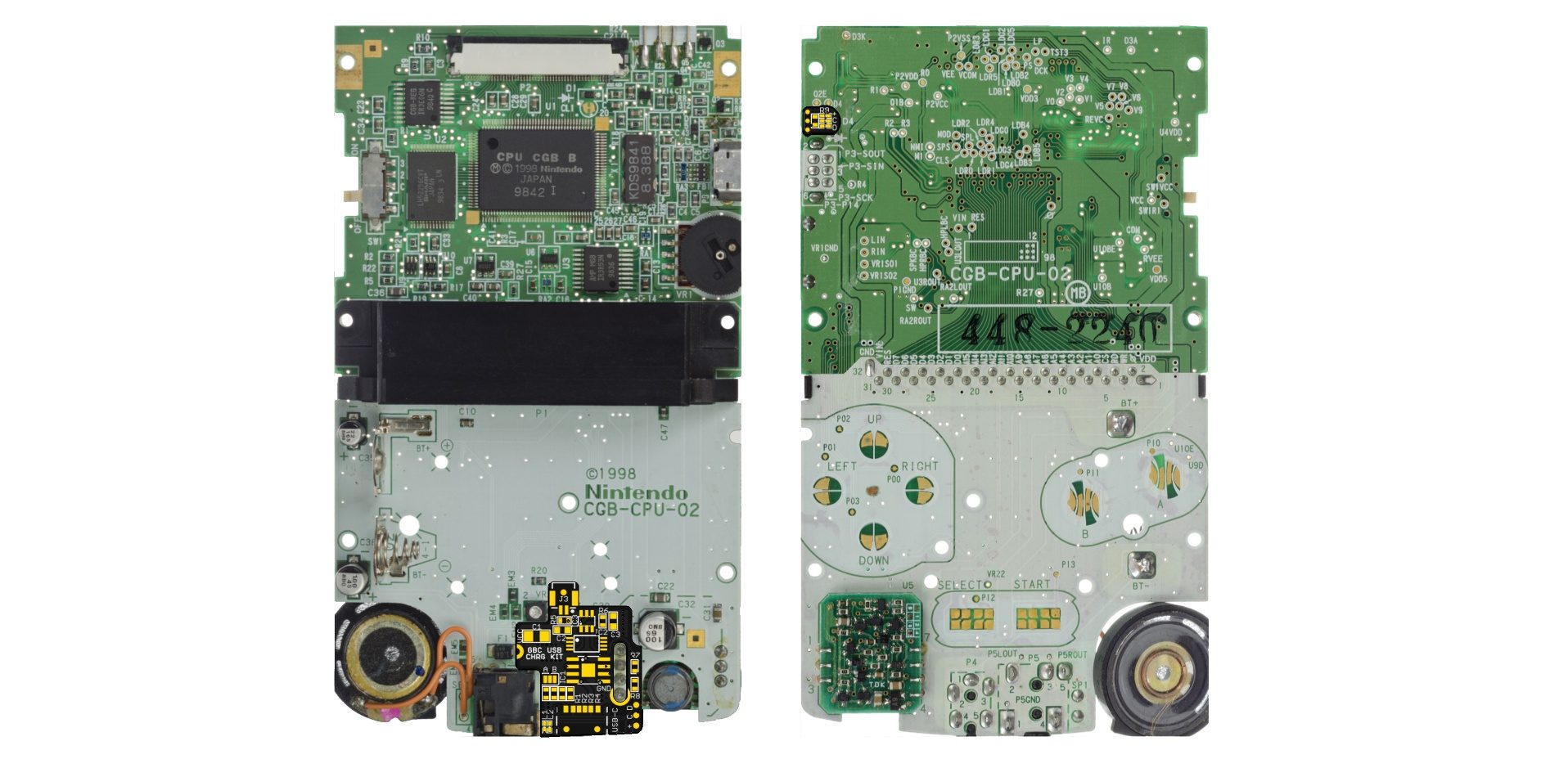
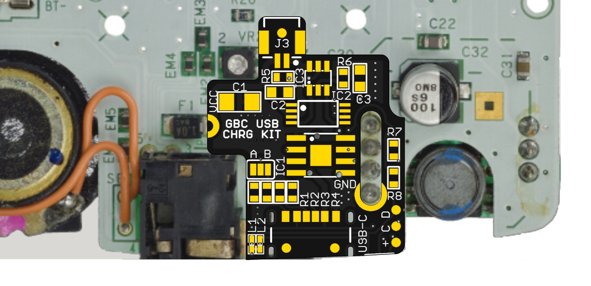
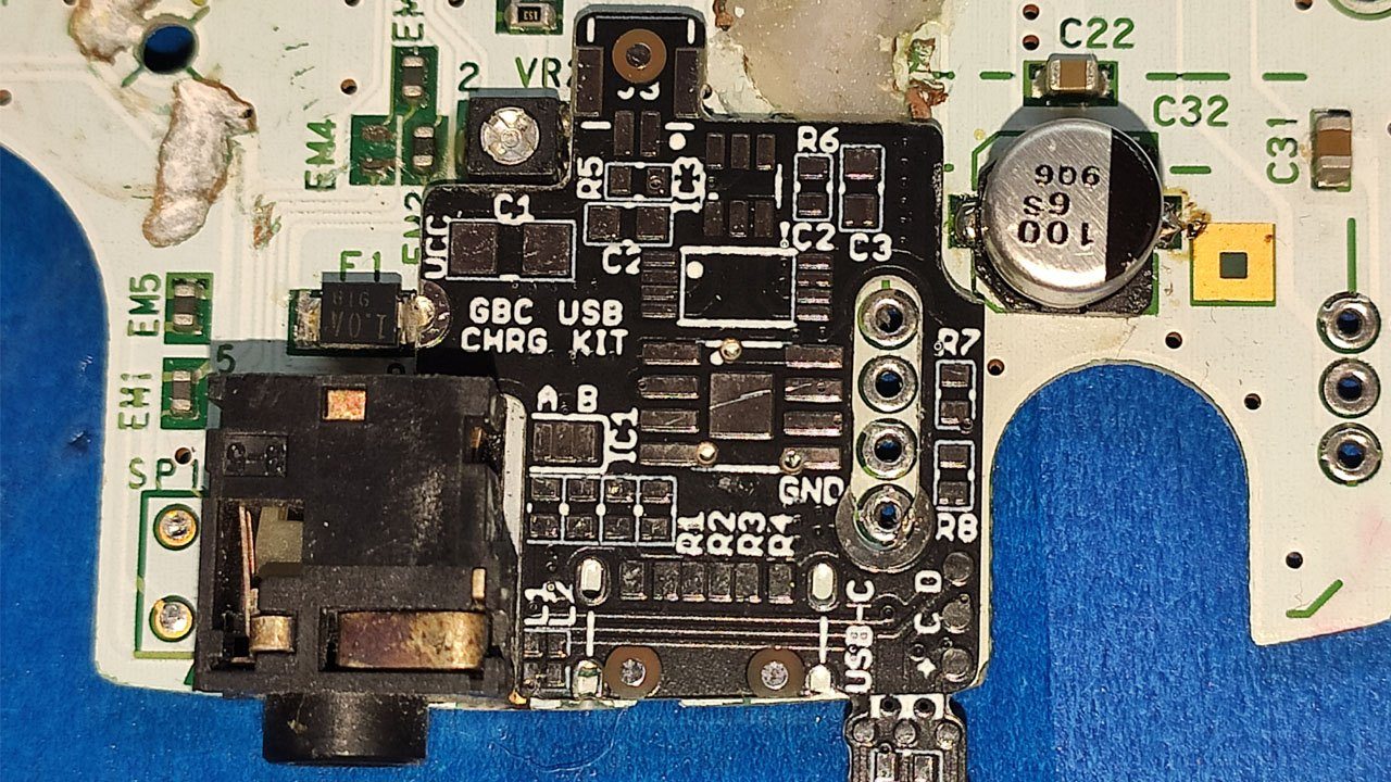
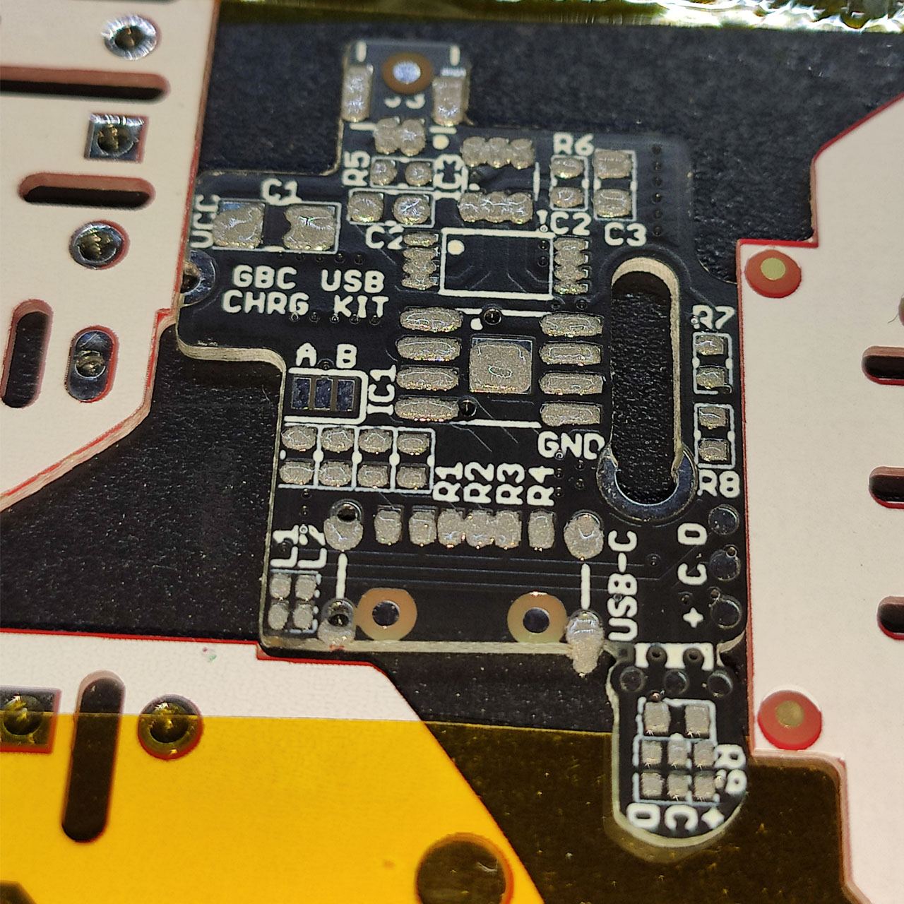
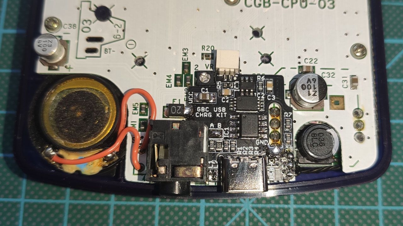
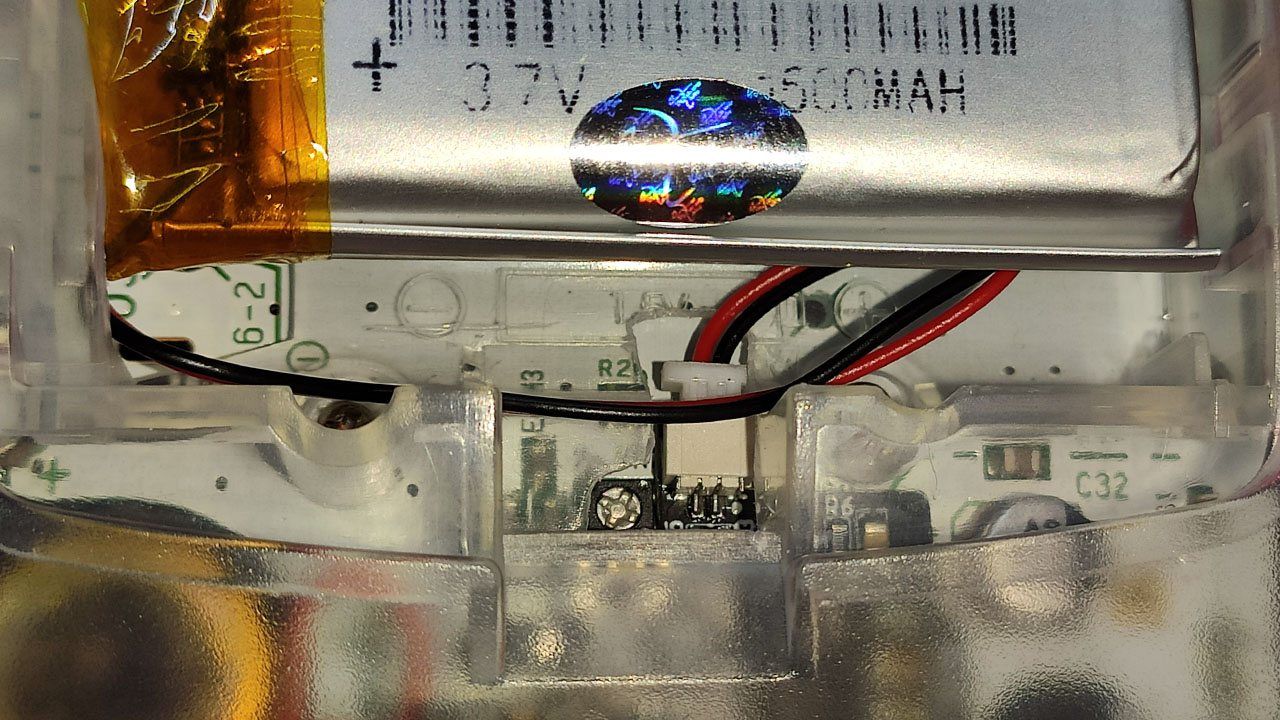
That is how the new board looks like on the original board. It is solder using 6 points: 4 from the original power connector (only for holding strong the new board) and 2 more for GND and VCC. The battery connector is on the top of the board, this allows to connect and disconnect the battery without needing to open the case.

Finally a short video of how it looks like:
If you have any of these still available, I am very interested.
Hello Jason,
Yes, I’m still having them. Each board is 10€ + shipping, where are you from?
Kind regards.
I’m also interested if you have one left, do you have an email address i can contact you on?
Hello Hdr,
I still have all of them. You can use this contact page for sending your address to me. With that, I can check how much is the shipping.
Hello, will you be making anymore? I would love to get one
Yes, I will have more soon 🙂
Hello, i’d also love one of these. I’m located in England, and if you see this and have one available you can contact me here: bullyhunter100@protonmail.com, thank you in advance.
I would love to order if still possible
I would like to have one, how can i get one? i’m from mexico
Hello im interested for the chip did you know the shipping price to Germany ?
If you do ever make more of these, I’ll definitely buy! Please let us know 🙂
I’m also interested. I had placed 2 in the cart from last batch, but didn’t place the order, next day when I was gonna place the order they were all sold out ☹️
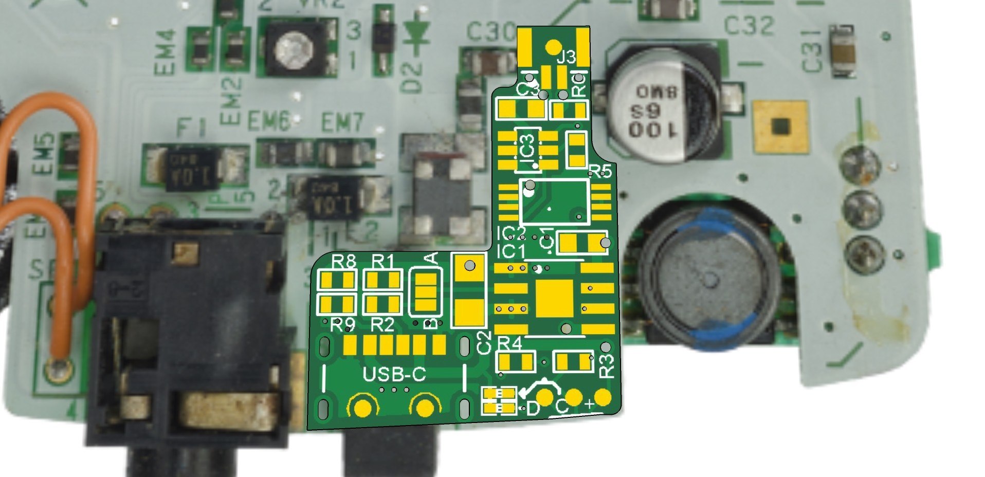
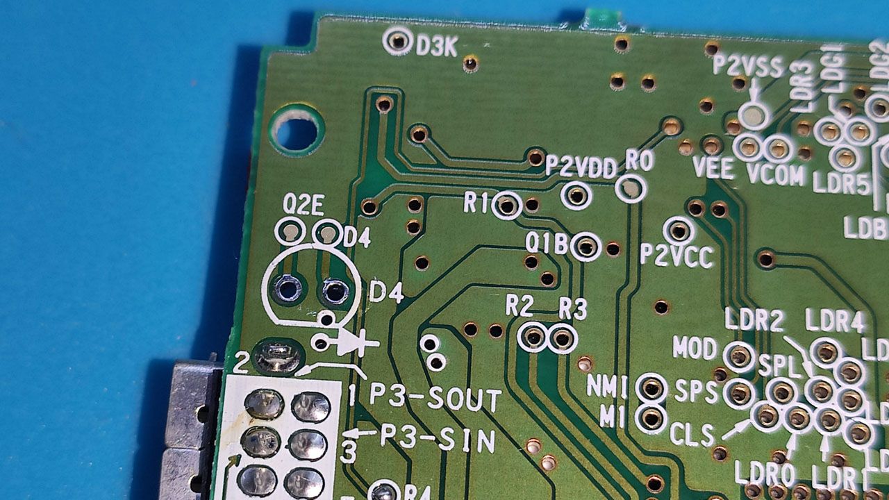
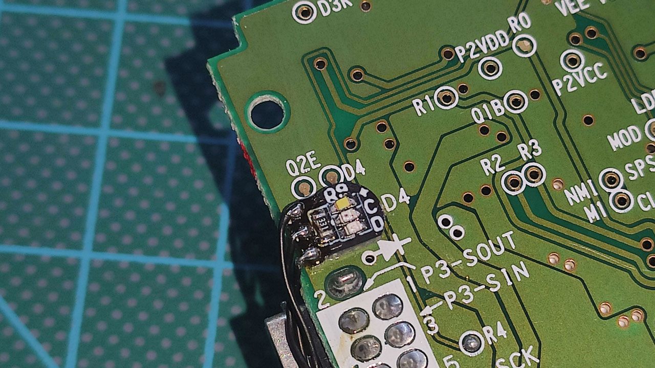
I just ordered one of these and thought I’d ask an odd question. I like to throw wireless charging coils on my gameboy builds and with this new board, I’m not really sure where to tack the wires for the coil, other than the little pins off the USB port itself. Is there another spot in your design where I could more easily add a couple wires for the coil? It’s just got to be at the beginning of the line, same as the input for the usb plug. I’d appreciate if you can think of somewhere, it’d just make it a lot easier than trying to attach to the plug itself lol. Thanks!
Hello ClarrFoxx,
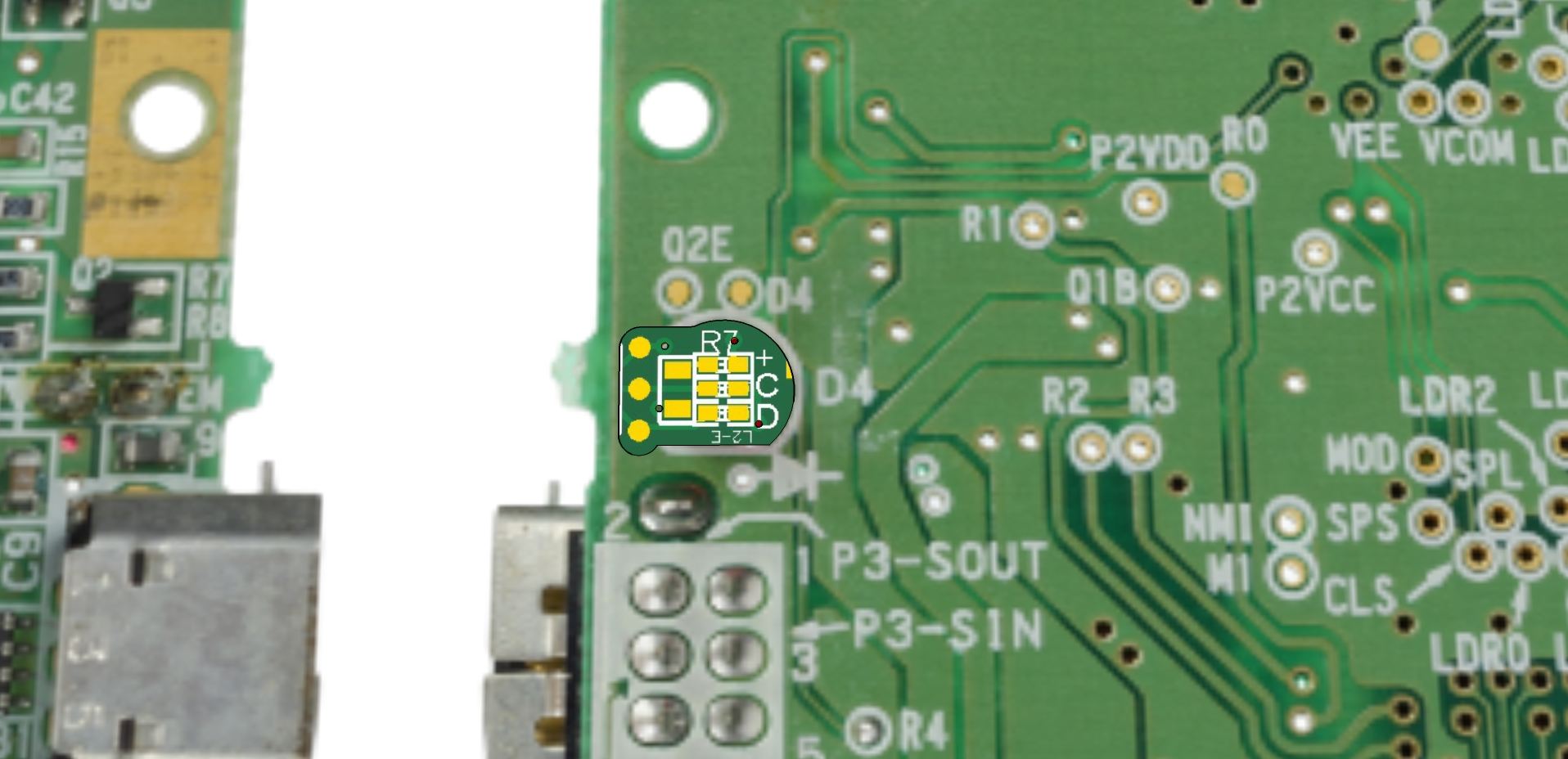
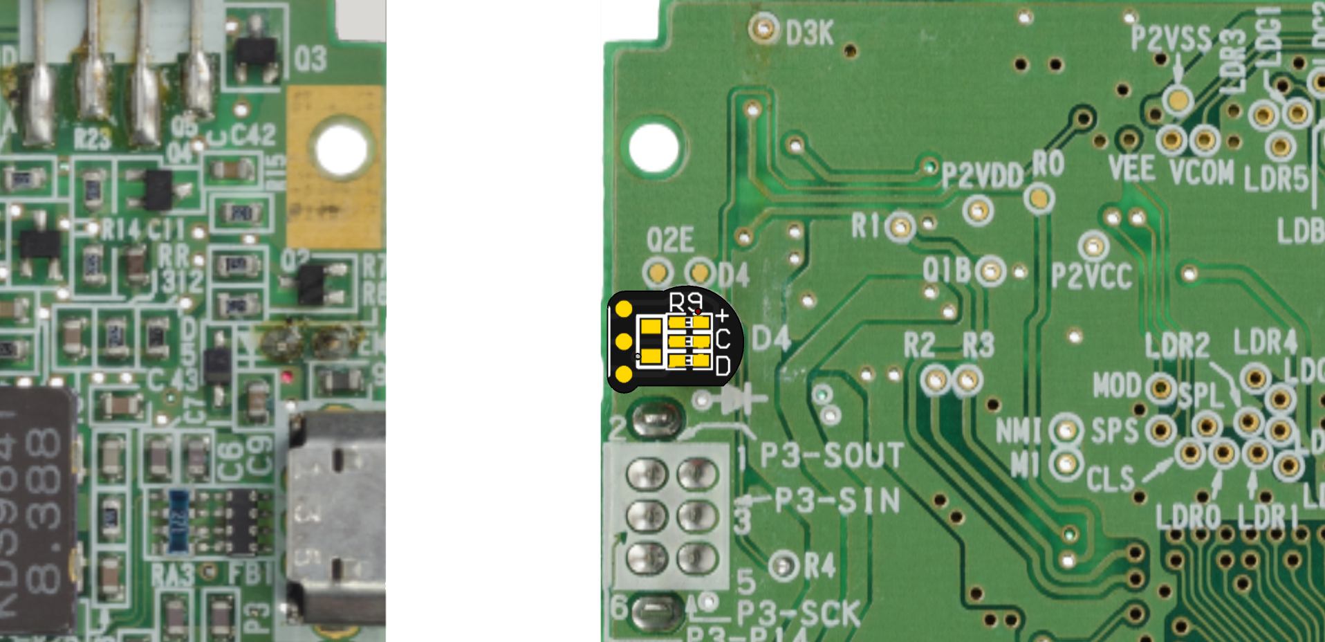
I think the easiest place for soldering your wireless charging coil can be here:
Kind regards,
What is the battery connector size? is it a jst 1.0?
I don’t know why you were in the spam folder.
The battery connector is JST SH1.0
Is there anything I can do to filter the power? I have a GBAmpV3 and the noise after adding this is super loud.
Hello Kyle,
I don’t have that audio module so I haven’t been able to try that. But I tried a original GBC and another with the charging module and both are noisy with earphones (with speaker are ok).
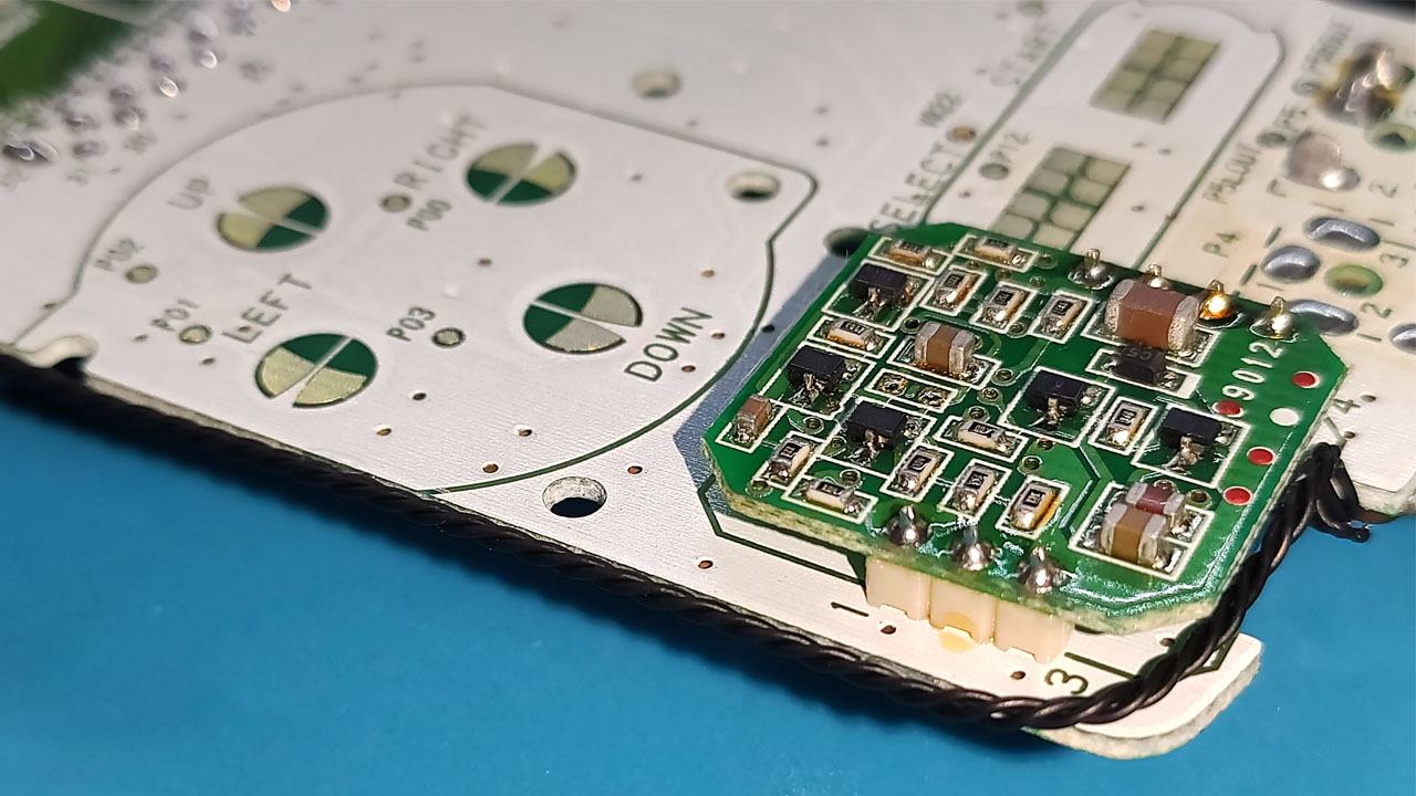
I have seen how people fix these kind of problems using some module for adding many capacitors like this:
https://www.pcbway.com/project/shareproject/GBA_Power_Cleaner.html
Or updating the old capacitors for new ones like this: (but I don’t know if this will fix the problem)
https://es.aliexpress.com/item/1005002400751621.html
Kind regards.
I ran into the same problem of crazy power line buzzing, but I don’t really care for the amps so I don’t have one. For context, this buzzing is present with the Q5 screen regardless of this little charge board, and I’m also using fresh caps and a nice bigger one for cleaner audio.
I just wanted to point out my simple solution for the others here. It’s not perfect, but it makes the system playable. So the left side of this board connects to the system’s fuse, right? What I did was take the fuse off and re-orient it so it’s vertical, left pad still attached as it was just moved, and added a diode between the now-free side of the fuse that this board used to sit against, and the pad the edge of the board is still attached to. For my system using a Q5 screen, I had to daisychain two diodes to solve the problem. It made the new power LEDs not work so I put the original back on, and it’s very dim. Once it goes out completely, you have about five minutes left. Oh and the q5’s battery indicator also doesn’t work properly with this workaround. But hey, gets rid of the buzz! It might be better if your system only needs the one diode instead of two.
Is this still available for purchase?
ez flash is a very battery consuming mod. If you use the original game, I think the battery life will be more than 12 hours.
Hello, only just found out about these power mod and just wanted to enquire if you’ll be making more?
Thanks
I would also like to try this mod out and would love to know if you will be making anymore. Thanks
Hi ClarrFoxx can you please bring more detail on how you solved the noise issue? I read you put 2 diodes where the fuse is, but can you specify which kind of diodes? Thank you!
I don’t recommend this mod, the noise it adds is unbearable, at least with an IPS screen. I dont have an audio amp, only an IPS and I cannot use my GBC thanks to this mod, the noise coming out of the speaker and earphones makes it unusable.. I wish I knew this before modifying my GBC since its almost impossible to revert the changes.. I have the bigger caps to filter the noise but they don’t work with this mod.. Also, you have to do a LOT of shell trimming.. be advised..
Hello Blehstor,
I don’t have here an unmodified GBC to compare with the modified GBC. But I can say my GBC doesn’t have an appreciable noise with the speaker, it has a bit noise by headphones, but I think it’s similar to an unmodified GBC. I will try to compare both this week.
On the other hand, GBC has more than 20 years, depending on the status of each one it may require change the capacitors, the speaker, power supply, etc.
About the shell, yes, it requires to trim it a lot, but it’s documented in the article, PDF, and video. I think everybody who bay it knows it. I mean, someone who doesn’t want to cut the shell I think the better option is to use rechargeable batteries.
Kind regards.
to Blehstor and anyone else with the noise issue: It is easily solved by replacing the voltage regulator with a new one. No diodes required anymore. The original regulator doesn’t send out a very stable current compared to a rechargeable battery, plus the Q5 screen seems to draw quite a bit more power than other IPS kits. I solved this issue by just replacing the voltage regulator with a new one sold by a bunch of different sites, one that is specifically made for all these new mods. Now it’s absolutely perfect. I don’t remember what specific site I got mine from, but it was likely handheldlegend. Good luck!
Oh thanks a lot for that info!! I have a pololu 5v regulator model U1V10F5 which I think can do the job! Thanks!
Thanks very much for your help ClarrFoxx!
After changing the original regulator with this one: https://www.pololu.com/product/2564 the noise has been solved completely!! This is a MUST for everyone with a Q5 screen!
Solved after changing original regulator with a new one! https://www.pololu.com/product/2564
Anybody have any issues with the led lighting? Red shows up fine on charge but no more green after first boot.
Hello Kevin,
If you are playing and charging at the same time, you may need to turn off the GB, otherwise the charging IC cannot detect there is not more consumption.
If that doesn’t help, you can try with another battery. Or use a multimeter and check if the green light is not damaged.
Kind regards